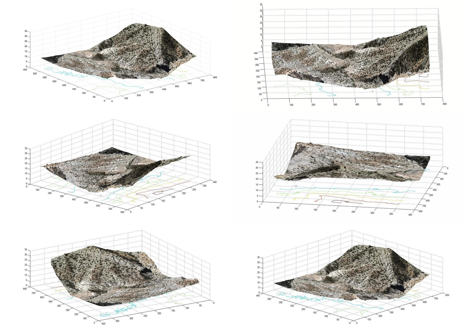
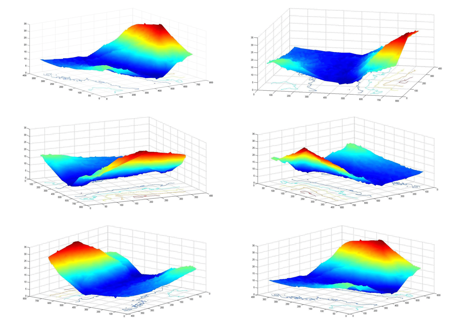
The purpose of this project is to estimate terrain depth and disparity map generation using aerial images with the help of stereovision techniques. One of the important problems in stereovision is stereo matching in aerial images is to calculate the Digital Elevation Model (DEM). The Main purpose of stereovision is to determine object disparity or computation of depth information. Stereovision can retrieve the relative depth of extracted landmarks with the help of least two images of a scene. Computing depth of landmarks in aerial images, it is necessary to provide feature correspondences in stereo images. DEM can be calculated using these correspondences. Additionally, several methods were proposed for the corresponding images. First, one is a local method that uses the neighborhood point to detect the similarity with those of the other images. Second method is global method. This method is performed using both point-based and regional. In global method, correspondences between all the points are found simultaneously. Point-based methods are more exact than region-based methods. Because, point-based methods correspond all the points in two images. Corresponding all the points is the first step for the best feature corresponding. Later on, the disparity map can be calculated. Once the disparity map is calculated, 3D-model of the observed scene can be produced. Calculating third dimension has a lot of useful information such as terrain of the earth. Moreover, detecting all corresponding points has high calculation cost. Therefore, the most important task is to increase runtime parallelism and to enhance the accuracy. Generating disparity map for stereo aerial images, it is common to use dense matching strategies to find feature point displacement in two adjacent images. To this end, researchers usually employ dynamic programming or graph cut method to estimate feature displacement along image scan lines. However, these methods are practical only for rectified images. For aerial images, which often have high resolution image rectification is an erroneous routine.
In our project, we first constructed a sparse disparity map using matched SIFT features and then the value of disparity for remaining pixels is calculated with the help of a bilinear interpolation.
(You can right-click on any one of these figures and save them for a higher resolution)

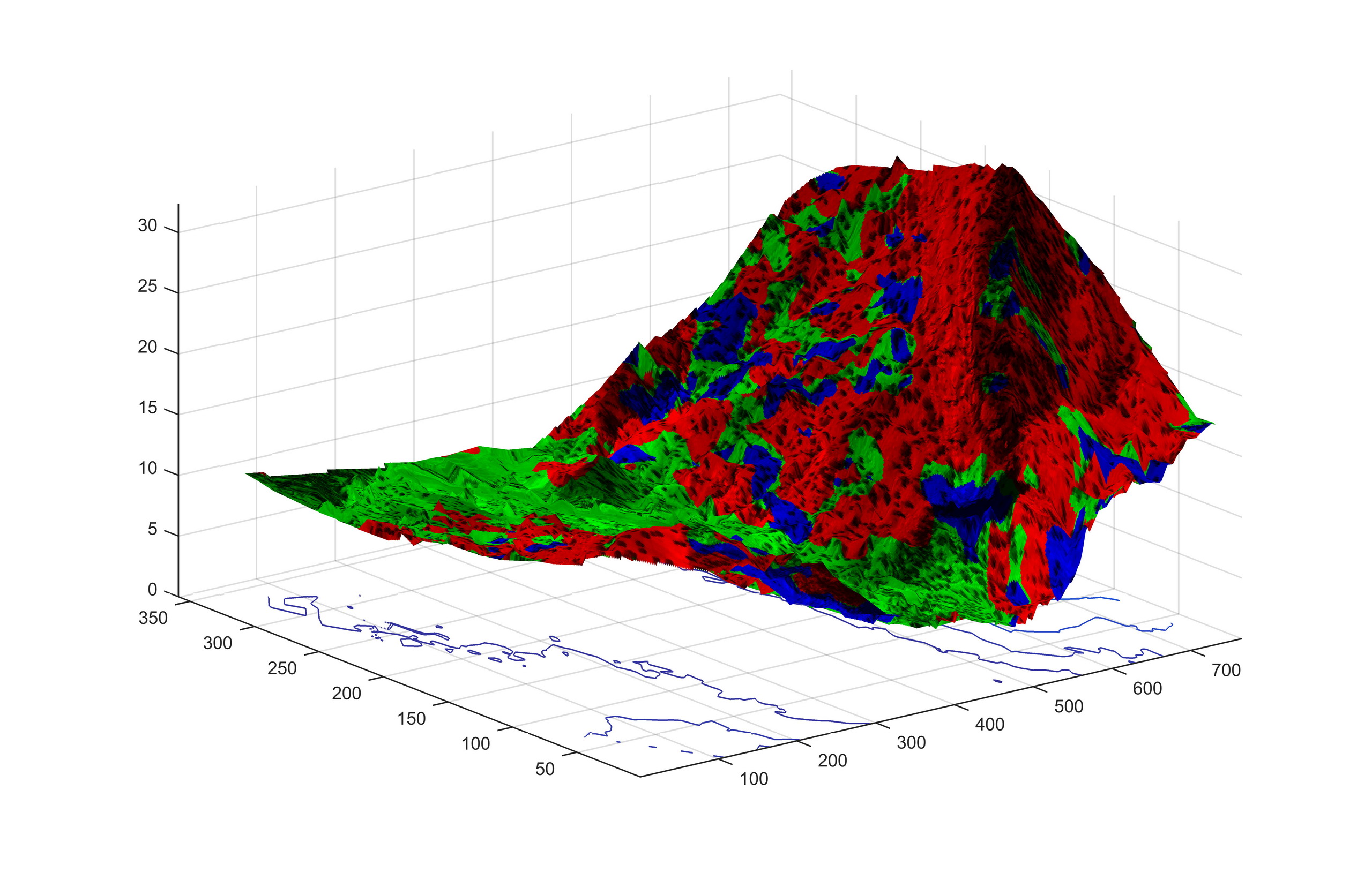
Figure 1 – Image set #1, Two different orientations

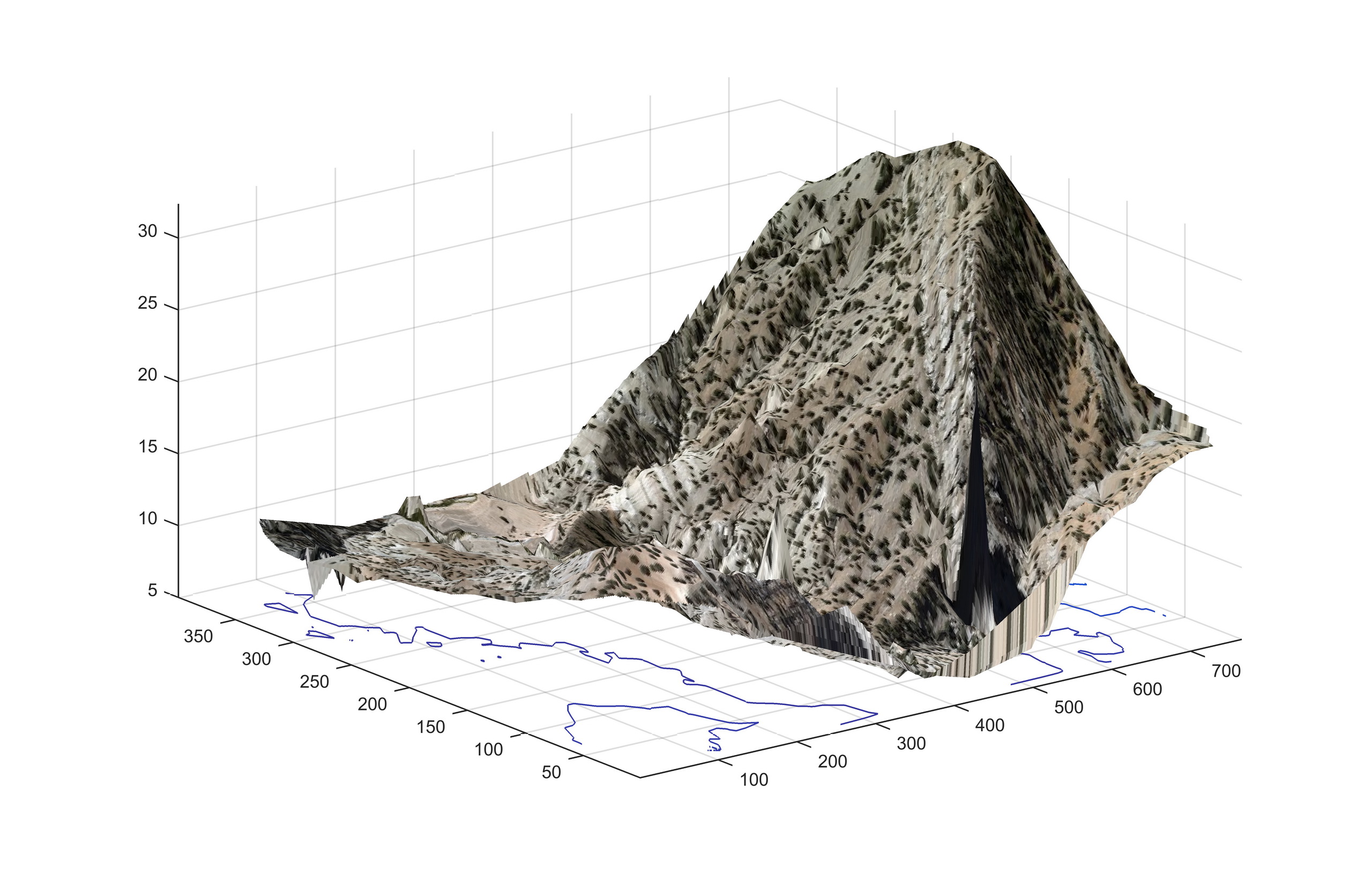
Figure 2 – Image set #1, Images above, containing an error spike

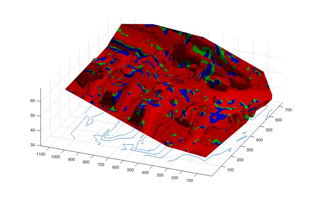
Figure 3 – Images set #2, captured and processed from a construction site
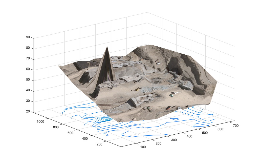
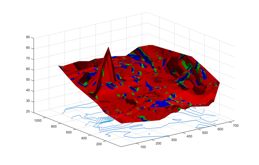
Figure 4 – Same as above, with an error spike

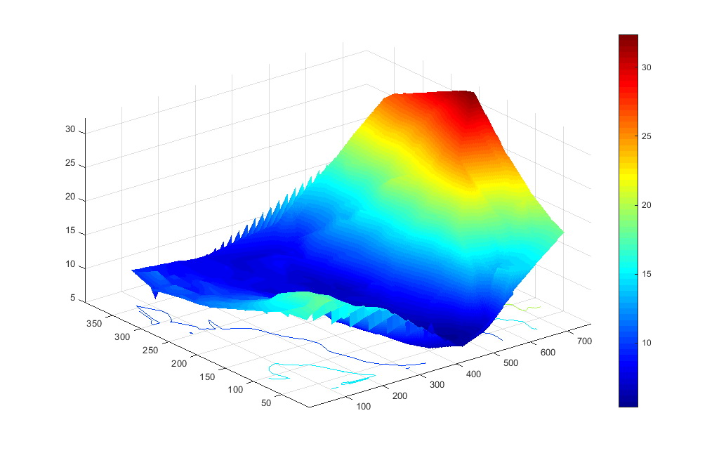
Figure 5 – Image set #3

Figure 6 – Image set #3, Matching
